The end of the line

Tidying junctions actions

When you draw a line unless you have the snap options set small gaps can appear at junctions / joins.

To rectify this you can either edit the line as described in the previous chapter or you can perform an Action.  NB Using actions before a major edit can save a bit of time on a badly or quickly drawn map.  Do it afterwards and it can make a mess of earlier edits – you have been warned.

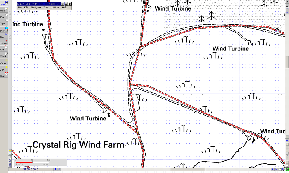
First we are going to create a new road and finish it short of a junction.  Just below and to the left of the Crystal Rig Farm label on the OS map, you should have an unmarked road.

  1. Navigate to the unmarked road, so it is in the centre of your view
  2. Now draw a line using the line tool from the turbine to the junction
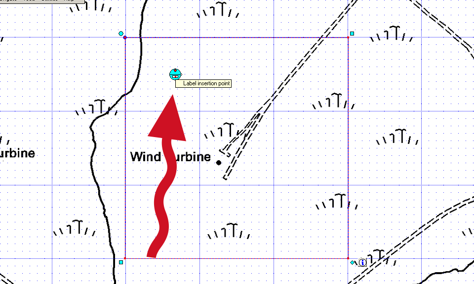
  3. Finish the line slightly short of the junction; use CTRL+E  top right hand stretch it back a bit if snapping is working correctly
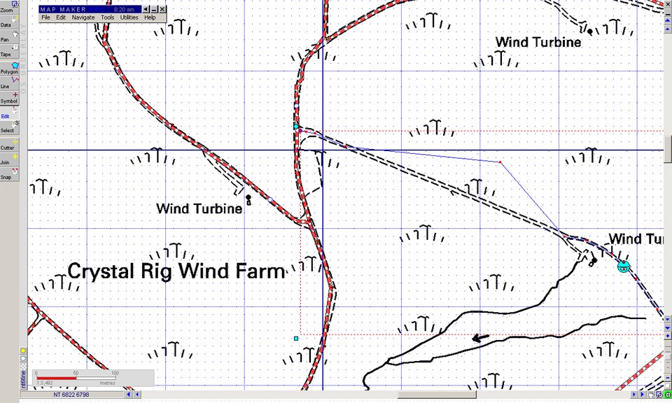
  4. Choose the select tool and select the new line and hold down SHIFT to also select the existing road
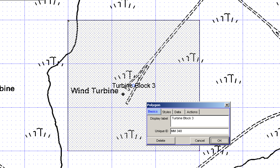
  5. Both lines are highlighted red and will appear in Edit > Show Selection Manager (a very powerful tool)
  6. Click the Actions tab and expand the Tidying option (click the +)
  7. Select Tidy line junctions (spaghetti processing) and check that the options
  8. Try a snap distance of 10 and gap of 10, and increase it gradually by 10, if nothing happens

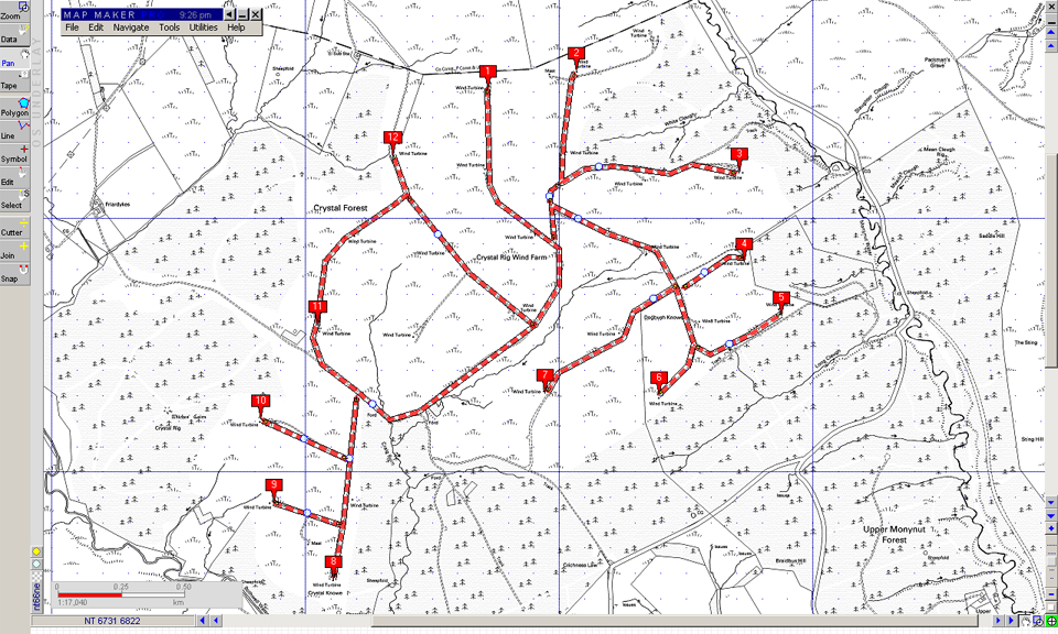
If all goes well a correctly formed junction should be visible.  You can now tidy up using CTRL+E.

Nota Bene

During this session, we have not saved any of the lines we’ve drawn.

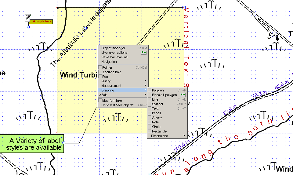
  1. Save the Live Layer by using the right click Context menu and Save Live layer as
  2. You’ll now see the data has been transferred from the Live layer to a static layer (if not try saving the project)
  3. If you save during an edit session remember that the options for adding new information
    • append or Add to live layer (from the Edit menu)
    • create a new version with a filename like: Roads003.dra
    • overwrite the existing version
    • create a completely new file

Edit those lines

Badly drawn map
Badly drawn map

If you draw lines at the scale of your map and take good care, you should always get a better result that in the illustration, which is badly drawn so that we can learn to use the edit tools.

Map Maker Pro offers a range of on screen editing options as well as a host of automation tools. Some of the editing options first:

  1. Simple Editing CTRL+E – you can move polygon boundaries, including common ones, create new vertices (select line and drag), delete vertices (click & delete).
  2. Double click a line to edit a single object – it will go blue and each vertex will be highlighted in red and a bounding box shown.
  3. The start and finish points can be dragged, but first up we are are going to select a middle vertex and drag it.
  4. Create new vertex by selecting a  point on the line that you want to drag, click to create a new vertex and just drag it into position.
  5. You can create as many vertices as you need to smooth a curved corner or work around complex features / boundaries.
  6. Delete a vertex by holding the edit pointer over it and clicking delete.

Remember Simple Edit allows you to move common boundaries in unison, which is very handy.

Sometimes you’ll find it easier to delete a line segment and redraw it. If you create your line segments in a structured way editing each segment is easier.  For example, it can be a good idea to stop at junctions and restart the segment and keep each segment fairly short.

Thin blue line
Thin blue line

As you become confident, there is nothing to stop you working on longer segments and panning the screen while you edit.  When you are done, your new spaghetti should look more like this.

Before we move it is worth introducing a new tool, the Selection Manager. which has a wider range of automation Actions.

Its a snap to draw lines

Markers are temporary and can be used to help you draw lines or just orientate yourself.  Markers can also be labelled and saved as layer.

In the following we are going to draw some roads to connect the markers, before deleting the markers.

We are going to make roads first:

  1. Select the draw lines tool or simply CTRL+L
  2. First of all select Edit > Live Layer Options > Snap to options > Snap to Live Layer
  3. Then Edit > Live Layer Options > Snap to options > Vertices or lines on click

Now we are ready to draw.  The lines you draw should snap to any lines you’ve just drawn, within 10pixels.

  1. Simply create a network of roads that connect the turbines.  It should look like the image, but don’t worry if you make mistakes, the idea is that we’ll correct these next.
  2. During line creation remember backspace to correct the last vertex and ESC to cancel the lot.
  3. Finally select an end point and then right click elsewhere to finish the line.
  4. Select the road style for now.

Zoom in and out if you want to, see that the snapping works.  If there are spaces between your lines the snapping options were probably turned off!  Or if the snapping hasn’t worked so well, make sure that you don’t create competing vertices where lines are to join up.

There's a clearing in the forest

In this exercise we are going to learn to use  the main drawing tools, save and edit data, label objects and features and create some map styles as we go.

First up we are going to head for a clearing in Crystal Forest, where a number of wind turbines are located.

Navigate to a clearing in the forest

So first of all let’s get the relevant OS tile (NT66NE) and navigate to Crystal Forest, which happens to be right at the centre of the tile.

  1. Start Map Maker and/or  clear the existing project
  2. Hit SPACE to call up the Project Manager
  3. Navigate  to the  TIF tile located in Public > Map Data > 10k_raster
  4. Remember to select for .tif files and then scroll to nt66ne.tif
  5. When you’ve added the layer, close the project manager
  6. If you are zoomed in close, zoom out the tile extent and zoom so that the middle 3 km squares are more or less centred and you can see the extent of the wind farm

Now we are going to load in some ready made markers, which should indicate the locations of 25 turbines.  If you cannot find the ready made marker file, don’t panic – it easy enough to create the markers yourself.

  1. Select from the  menu Edit > Markers > Load points as markers
  2. Look for the file Turbines.dra
  3. No luck?  Place markers on the map yourself.
  4. The markers merely identify the 12 outer turbines.
  5. To create markers, simply hold the cursor pointer tool over the spot and press the letter M (don’t click!) and keep going until you’ve got the 12.
  6. If you make a mistake, its CTRL+E and the select the bottom of the marker.  In the Dialogue choose the Actions tab and delete. You can clear all the markers in Edit > Markers > Clear markers or  save the markers Edit > Markers > Save markers (watch out as they will become a layer.)

If everything is looking like it should, move on to the next session.

Labelling and Text Basics

Change the Label Attribute

There are 2 main sorts of labels and these are different from the so-called map furniture mentioned earlier (Titles and legends etc):

  1. the label attribute associated with an object and
  2. free standing objects or labels in their own right.

A further label type, the marker, is a temporary aid that can be useful during the drawing process.

The attribute label associated with an object is accessed via a single click (CTRL+E and select the object). The properties of the object are called up where you make changes to any of the properties of the object. Click the basics tab, if this is not your default, and rename your object. Remember that this label is only shown if the layer in question is set to show labels. You can select a different style for the label or create your own style in the Styles tab.

Label Insertion Point

If you want to move the position of the object label, you must go into Edit mode (CTRL+E). Double click the object and the label insertion point should be highlighted clearly in the middle of the object. You can pick it up, alter the angle of the text and adjust the justification. It is a bit fiddly at first, but persist because it works quite well.  When you are done simply click off the object. You can perform all the other edit operations, like rotate, move and stretch at the same time.

Other annotations are done via the Draw options, in the context menu – we’ll deal with symbols separately.  We have:

  1. Text
  2. Arrow
  3. Dimensions
  4. Note

Adding Labellings
Adding Labellings

Text objects are essentially vector objects, with a beginning and end used for on-map annotations.  You can obviously set a text style and you can alter the text height (in metres!) and the justification, which opens up neat options such as stretching the text between the to end points or following an S or other shaped curve.

Arrows allow you to label a complex object with ease. Both Text and Arrows can be edited and moved just like other objects. Arrows and text will be rendered in print and on screen.

Dimensions are handy because they automatically measure the distance between points and then render the measurement on the screen and a printed map.  Dimensions, like text, can be styled.

Notes are a different sort of label, and although are very versatile are only of use to the map maker as the Notes are not visible on the printed or otherwise published map.  Notes can be anything from a text document to an image or a web page.

Finally Markers: use these only to set out temporary points that you want to join up during a drawing session.  You can edit labels, and join them up or delete  via the Actions tab.  To add marker place the cursor on your map and click M.  To edit a marker and access the Actions tab:  CTRL+E and click on the marker’s base.